Data View
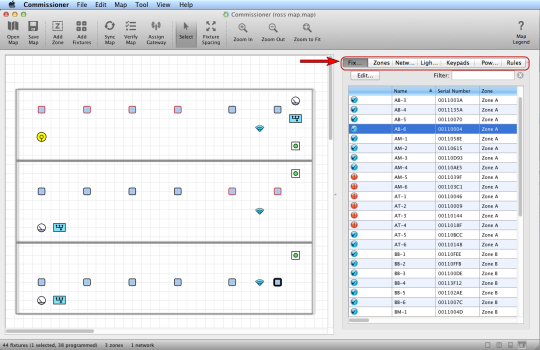
Data view displays the map file information in a sortable list format.
Fixtures appear both on the map grid and in the fixture tab. However, the fixture tab provides more detailed data, including status icons, fixture names, serial numbers, zone assignments, and more.
Similarly, data view displays at-a-glance details for zones, networks, lighting gateways, keypads, power gateways, power meters, and rules.
Status Icons
In data view, the following status icons are the same for all fixtures, zones, and networks (keypads, power meters, and power gateways do not display status icons):

|
The fixture, zone, or network requires configuration. |

|
The fixture, zone, or network is fully configured and synced. |

|
Settings have changed and must be synced. |

|
The settings were synced, but Commissioner still requires a verification. Run the Verify Wizard (see Verify the Map). |

|
The settings were not synced, and Commissioner still requires a verification. Run the Verify Wizard (see Verify the Map). |
Tip: In the fixtures tab, hover the mouse pointer over a column heading for a definition of the data in that column. Additionally, hover the mouse pointer over certain fields to view map file settings versus fixture settings (if they don't match, sync the map).
Editing a Fixture
Double-clicking a fixture in the list displays that fixture's Edit Configuration dialog box, where you can change the fixture's name, zone assignment, and description:
Additionally, you can perform the following advanced functions:
- If a DLA is connected to DLA-CA/FA, you can select a 0-10v profile for the fixture.
- If the fixture has been calibrated for daylight harvesting, you can enable or disable the daylight harvesting capability of that particular fixture.
- Configure the fixture as a Coordination Master, which enables unified control of multiple fixtures when the Coordination Master fixture detects occupancy (see Coordinated Control Setup).
- Click the [+] icon to show the currently assigned network. If you know that the currently assigned network is incorrect (for example, if you added a new fixture to the map by entering the fixture serial number but accidentally left the factory default network assigned), you can manually change the network here. Otherwise, if you are not aware of an error, do not change the network.
The zones tab displays following detailed information including status icons, zone names, network assignments, fixtures per zone, room assignments, and more.
- Status icons
- Zone names
- Network assignments
- Fixtures per zone
- Room Assignments
- Zone rules (active power level, inactive power level, sensor delay, ramp up/down speed, temperature)
- Safety lighting activated (Y/N)
- Ignore occupancy sensor activated (Y/N)
- Coordinated enabled (Y/N)
- DH enabled (Y/N)
- Text descriptions (if available)
Tip: Zones are color-coded: In the map grid, all fixtures in the same zone display as icons with the same fill color.
Editing a Zone
Double-clicking a zone in the list displays that zone's Edit Configuration dialog box, where you can change the zone's name, network assignment, room assignment, description, rule settings, and advanced settings:
Zone Rules
The active power level, inactive power level, and sensor delay are applied to all fixtures within the selected zone.
- Active Power Level: The amount of illumination delivered by a light when there is activity detected below that light. The typical setting is between 90 and 100.
- Inactive Power Level: The amount of illumination delivered by a light then there is no activity detected below that light. The typical setting is between 0 and 10.
- Sensor Delay: The length of time, during which no activity is detected, before a light switches from the active power level to the inactive power level.
- Ramp Up Speed: This speed determines how many seconds a fixture will take to ramp up illumination from off (0%) to full brightness (100%). Select a range from 0-300 seconds (0-5 minutes). The default setting is 0, which disables the dim ramping feature.
- Ramp Down Speed: This speed determines how many seconds a fixture will take to dim from full brightness (100%) to off (0%). Select a range from 0-300 seconds (0-5 minutes). The default setting is 0, which disables the dim ramping feature.
- Advanced Zone Settings
- Ignore Occupancy Sensors: Check this setting only if the facility has opted not to use occupancy sensing for the selected zone. For example, some aircraft maintenance hangars do not use occupancy sensing.
- Safety Lighting: Check this setting to allow a minimum active/inactive light level (specified in the LightRules Administration General Settings).
- Coordination Enabled: Uncheck this setting to disable coordinated control across the entire zone.
- Daylight Harvesting Enabled: Uncheck this disable to enable daylight harvesting across the entire zone.
The networks tab displays following:
- Status icons
- Network IDs
- Wireless network data
- Gateway assignments
- Gateway serial numbers
- Gateway firmware version(s)
- Fixtures per network quantities
- Text descriptions (if available)
Editing a Network
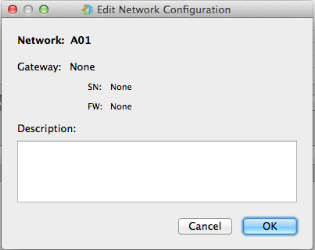
Double-clicking a network in the list displays that network's edit page, where you can edit the description or delete the lighting gateway assignment:
The lighting gateways tab displays following data:
- Name
- Network assignment
- IP Address
- Serial Number
- Product
- Firmware version
- X and Y coordinates on the map grid
- Description
Double-click on a lighting gateway to access its settings, where you change a lighting gateway's name and network.
The keypads tab displays following data for each keypad:
- Keypad name
- 8-digit Serial Number
- IP address
- X and Y coordinates on the map grid
- Description
Double-click on a keypad to change a access its settings.
The power gateways tab displays following data for each power gateway:
- Power gateway name
- Manufacturer and model number
- MAC address
- Static IP address or DHCP configured
- X and Y coordinates on the map grid
- Description
Double-click on a power gateway to access its settings.
The power meters tab displays following data for each power meter:
- Power meter name
- Manufacturer
- Model number
- 6-digit serial number
- Meter group
- Modbus address (Modbus is the communications protocol used by power meters)
- Current Transformer (CT) size, in amps
- Power gateway assignment
- X and Y coordinates on the map grid
- Description
Double-click on a power meter to access its settings.
The rules tab displays the rules of each zone.
- Active power level
- Inactive power Level
- Occupancy sensor delay
Tip: To re-size map view or data view, click-and-drag the small dot in the column.


