Configure-then-Hang
Using this method, the map file is built before the fixtures are installed. Once onsite, the fixtures are installed in the locations specified by the map.
- Use this method when the customer is not comfortable with fixtures temporarily operating on default settings.
- The fixtures must be installed in their specific, assigned physical locations, as per the map file.
- This method is suitable for any size install, especially when a detailed sticker map is not available.
Step 1: Create a map "skeleton" by adding empty zones to the map:
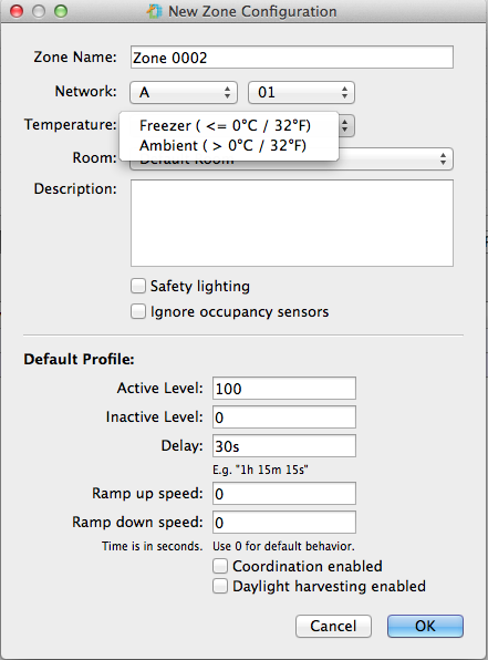
- Click Add Zone.
- Using the Pre-installation Worksheet for reference, enter the zone name, network ID, temperature, and room assignment.
(missing or bad snippet) - Specify the default zone rules for active power level, inactive power level, and sensor delay (minimum 30 seconds).
- (Optional) Check the Coordination enabled check box to allow coordinated control within this zone. See Coordinated Control Setup for more information.
- Click OK.
- Repeat for all zones listed in the pre-installation worksheet.
Step 2: Import a Background Image
- Create a PNG, JPG, or TIFF file depicting the floorplan of the facility (typically exported from a CAD program).
- From the File menu, select Load Background Image.
- As needed, from the View menu, select Set Background Scale to adjust the image size and, as needed, use Set Background Transparency to make the grid visible underneath the image.
Tip: Before you import the background image, use image editing software to "clean up" the image by removing sprinkler systems, captions, etc.
Step 3: Add fixtures to the map
- In the toolbar, click Add Fixtures.
- Select Add fixtures to the map by: connecting to them using a USB cable.
- Click Next.
- Review the fixture information and then click Program Now to proceed with programming.
- Once programming is complete, disconnect the USB cable, and then click Add Another Fixture (or click Done).
- Adjust the light bars, as desired.
- Using a grease pencil, mark the fixture with its network, zone, and name on the top side of the frame or end-plate.
- Add the extra serial number label to the sticker book and repeat steps 4-7, as necessary, for all fixtures.
Step 4: Add lighting gateways to the map
- In the toolbar, click Assign Gateway.
- Select Manually add gateway information to the map and then click Next.
- Enter all lighting gateway information, associate the lighting gateway with the desired network, and then select the lighting gateway type (refer to the lighting gateway labeling for the lighting gateway "Item" number.
- Click Finish and repeat steps 1-4 for all lighting gateways.
Step 5: Install and Verify the fixtures
- Install the fixtures throughout the facility, in the correct physical locations as specified by the map file.
- Connect the Digital Lumens USB Wireless Adapter to your computer.
- Click Verify the Map and follow the verify wizard to check the map file against the programmed settings of each light. If the map file and fixtures are out of sync, you will see red check mark icons next to the fixtures that you need to update.
Tip: When adding a fixture, you can either add a new fixture icon to the map grid, or you can select an existing placeholder fixture that you previously positioned on the map grid. For example, you could use the Add Fixture Grid feature to populate the map with blank fixtures and then update those fixtures at a later time.
Note: If available, 3rd party DALI controls are auto-detected during commissioning. Enter power numbers in watts (low end and high end) for all 3rd party DALI controls.